Since questions seem to come up quite a bit regarding this system, I decided to put together a quick guide on the proper assembly order of the components in the
LC/FLEX 3401 Interchangeable Backing Plate System. This guide specifically shows the user where to install the shims when using the 6" backing plate with the system.
Step 1.
After you have removed the factory supplied backing plate from your 3401, you are ready to begin installing the LC Interchangeable Backing Plate System. Your Flex should look like this:

Step 2.
Install the LC drive plate adapter onto your Flex ensuring that the slow fits snugly over the raised portion of the spindle. Your Flex will now look like this:

Step 3.
Place the thin shims in the center of the drive plate adapter. This is how your Flex should look at this point:

Step 4.
Place the 6" backing plate onto the drive plate adapter ensuring that you have aligned the tabs from the backing plate into the slots in the adapter plate. There should be no gap between the two plates. Now your Flex looks like this:
Step 5.
Place the washer (some are calling this a thick shim) in the center of the backing plate. You're almost done and this is what you should see:

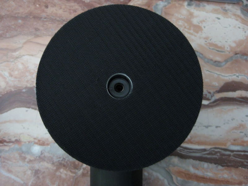
Step 6.
Insert the socket-head cap screw through the entire assembly, thread the bolt into the spindle, and tighten. You have now completed the assembly of the LC Interchangeable Backing Plate System. Here is a picture of the finished assembly:

[/IMG]
I hope this helps clear up some of the confusion regarding how to properly install this backing plate system on the FLEX 3401.


 Thanks:
  Likes:
  Dislikes:

Originally Posted by WRAPT C5Z06


 Reply With Quote
Bookmarks